By clamping as far back from the probe shank as possible, the MPM Probe Mount 1As allows researchers to maximize the density of probes in multi-probe neural recording experiments.
Mount Maximizes Density of Neuropixels 1.0 Probes in Multi-Probe Recording
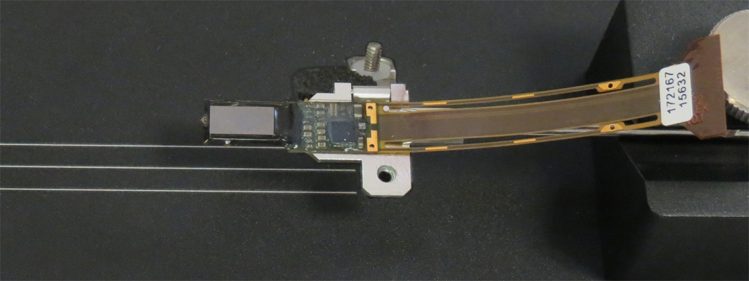
New Scale’s MPM-Probe Mount-1As clamps Neuropixels 1.0 probes at the end of the circuit board, where the circuit board attaches to the probe flex cable.
By clamping the probe as far away from the shank as possible, rather than by the silicon spacer or dovetail cap, this probe holder allows researchers to maximize the density of probes in their multi-probe neural recording experiments.
The probe mount design was created in collaboration with the Allen Institute, supporting their development of the six-probe MindScope rig (see photo) and 24-probe next-gen insertion system. Both rigs use New Scale micro manipulators and multi-probe control software.

Photo courtesy Allen Institute
How to Install and Align Neuropixels 1.0 Probes in the MPM-Probe Mount-1AS
Due to manufacturing variations in the circuit boards of the Neuropixels probes, researchers often need to add shims between the circuit board and probe holder to achieve proper alignment. New Scale’s new probe Alignment Fixture has been demonstrated to be an excellent tool for alignment of both Neuropixels 1.0 and 2.0 probes in their respective probe mounts.
This article describes how to align a Neuropixels 1.0 probe in New Scale’s MPM-Probe Mount-1AS probe holder using the new Alignment Fixture. (For information on Neuropixels 2.0 probes refer to this related article.)
1. Remove the base of the probe holder
Use a screwdriver to loosen the two screws in the MPM-Probe Mount-1AS base. Remove the probe holder from the base.

2. Insert the probe holder in the Alignment Fixture
Loosen the thumbscrew of the Alignment Fixture. Slide the probe holder into the v-groove. With the probe holder in the orientation shown, tighten the thumbscrew.

3. Open the clamp
Use a screwdriver to loosen the screw in the probe holder. Open the probe clamp.

4. Identify the guide features
The probe clamp has a raised edge and a post to aid in probe installation.

5. Install the probe in the holder
Place the slot of the probe flex cable over the post on the probe holder. Place the edge of the probe’s PCB flush against the raised edge.

6. Close the probe clamp
Close the probe clamp and tighten the screw.

7. Check probe alignment
Check the alignment of the probe shank under a microscope, using the reference lines in the alignment fixture. With the probe horizontal to the alignment fixture (left view below), use your fingers or tweezers to nudge the probe into alignment before tightening the Philips head screw. The probe holder can be rotated 360° in the alignment fixture. Only the two orientations shown below are needed to check for proper alignment.

8. Adjust alignment, using shims if needed
Due to manufacturing variations in the probe circuit boards, the probe may be bent or misaligned with the bottom of its PCB. In this case, adding shims between the PCB and the probe holder will straighten the probe angle for proper alignment. See the photo below, showing the probe perpendicular to the alignment fixture.
Photo courtesy Ahmet Arac, UCLA
For shim material, we recommend stacking pieces of Kapton tape. This tape is ~24 micron thick and can be stacked to precisely control thickness and angle. A 3/8” wide tape will fill the pad space on the mount. Tape options include:
- One-sided adhesive tape: https://www.mcmaster.com/products/polyimide/masking-tape-for-electronics-8/
- Double-sided adhesive tape: https://www.mcmaster.com/products/double-sided-tape/electrical-insulating-mounting-tape/
The MPM System probe arm is designed so that the probe arm is centered to the alignment of the probe. Using tape allows you to correct the probe alignment while adding no or minimal offset. We suggest starting with a single layer of double-sided Kapton tape. Measure the length of tape needed, then cut it to length.


After adding a layer of tape, re-tighten the probe clamp’s screw and check alignment. Continue to apply layers of tape incrementally until the probe is aligned.
If more extreme adjustment is needed, you can use shim stock. You can buy precise stock sizes and cut them to size:
Shim stock is non-adhesive, so we suggest adding an additional layer of Kapton tape on top of the shim stock to aid probe installation.

Next Steps
Once you have used the alignment fixture to install and align your probes in the probe holder, the next step is to insert the rod of the probe holder into the mount bracket on the motorized stage assembly. Please refer to the how-to videos and user manuals on the MPM User Portal.
Some users have found the need to rotate the probe holders in the mount brackets, in order to achieve close spacing of multiple probes without collisions. Allow slack in the probe flex cable when rotating the probe. Here’s an example from the Allen Institute:

For more information
Learn about other probe mounts including Neuropixels 2.0 probe mounts
Get probe mount drawings (registration required)
Contact us with questions or to order probe mounts
Multi-Probe Micromanipulator System
The Alignment Fixture and MPM-Probe Mount 1AS are designed for use with New Scale Technologies’ Multi-Probe Micromanipulator (MPM) system for precise, automated positioning of multiple silicon neural probes.
The compact design enables independent positioning of multiple probes in the smallest space, with ample clear area for a virtual task environment. Automatically and independently move each probe to the optimum location in the brain.
