
Linear Micro Stages
M3-LS Linear Smart Stage
Micro positioning stage with embedded controller
The M3-LS Linear Smart Stage is a direct-drive, high-precision micro stage with built-in controller. It is designed for fast, simple integration into miniature OEM systems. This “smart stage” has all drive electronics integrated right into the compact stage housing – no external board needed! It offers unmatched precision, stability and ease of use.
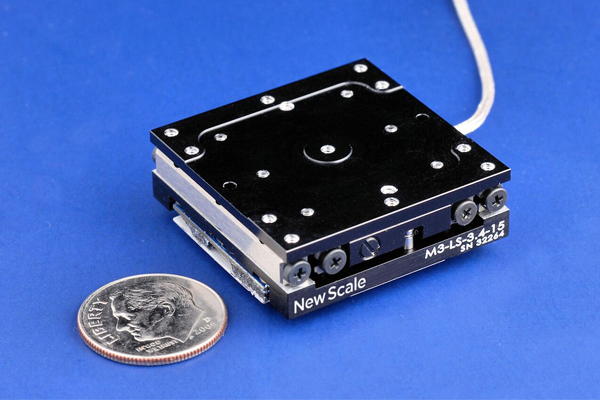
M3-LS-3.4-15 Linear Smart Stage
This longer-travel, higher-load micro stage with integrated controller has low power use and 15 mm of travel.
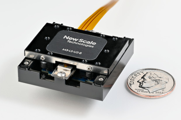
M3-LS-U2-8 Linear Smart Stage
This high-speed micro stage with integrated controller is optimized for high-volume production. It has 8 mm of travel.
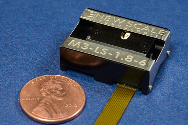
M3-LS-1.8-6 Linear Smart Stage
This ultra-compact micro positioning stage with integrated controller has low power use and 6 mm of travel.
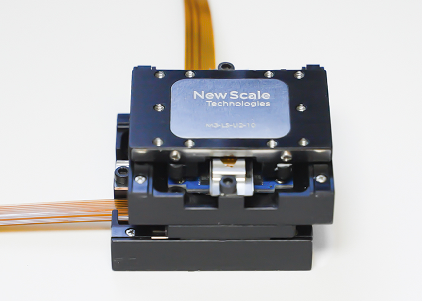
Multi-axis Systems
Easily configure multiple M3-LS microstages into XY and XYZ stage configurations.
ADVANTAGES
Smallest Size – Fastest Integration Into OEM Instruments
- Integrated smart module: no separate electronics – USB, I2C or SPI interface
- Small size: from 29 x 20 x 10 mm to 32 x 32 x 11 mm including controller
- High resolution: 0.5 µm
- Long stroke: 6 mm, 8 mm, and 15 mm
- Absolute encoding: no homing needed
- Low voltage, low power use
- High repeatability and low runout
- Quiet: so quiet you can hear a pin drop (video)
Unmatched precision, stability and ease of use
The piezo-driven positioning stage has 0.5 µm resolution for precise, repeatable positioning of optics, probes, sensors and more. Absolute encoding removes the need to home the stage on power-up, eliminating errors and disruptions in processes and experiments.
The M3-LS micro stage has high stiffness and lateral stability, no backlash, and less than 10 µm runout over its full travel range.
Direct input via USB, I2C or SPI
The M3-LS Smart Stage – a linear stage with embedded controller – accepts direct input of simple high-level motion commands. It is the only linear micro stage that can be driven directly from a system processor via standard I2C or SPI interface.
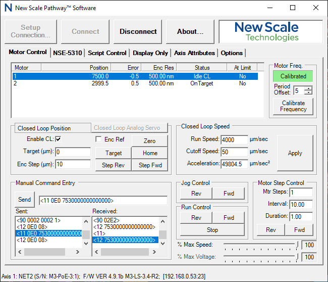
Alternatively, a USB adapter enables connection to a PC, with New Scale Pathway™ software providing an easy-to-use graphical user interface. You can control multiple positioning stages from a single screen for interactive operation. Employ the intuitive script generator to create command sequences for automated operations.
Low voltage, low power use for hand-held systems
The integrated piezoelectric motor holds position without using power. The internal electronics can be switched to sleep mode for extreme low-power applications. Unlike other piezo stages, there is no internal high voltage.
APPLICATIONS
A tiny all-in-one positioning stage that can be powered by standard batteries, the M3-LS linear micro stage is ideal for motion in hand-held and portable instruments.
- Create miniature microscopes, spectroscopy and DNA sequencing instruments.
- Develop smaller wearable medical devices and point-of-care diagnostic systems.
- Miniaturize systems for micro assembly and biomedical probing or sampling.
- Use in high resolution tuning, laser beam steering and targeting systems
- Miniaturize UAV/UGV controls and optics.
- Develop miniature camera systems and more.
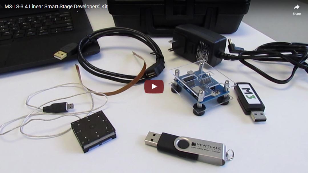
Developer’s Kits
M3-LS micro stage developer’s kits provide easy evaluation and prototyping with M3-LS Linear Smart stages.
All kits include the linear positioning stage with embedded controller, and a USB adapter with powerful New Scale Pathway PC software for easy evaluation, system development and prototype testing.
New Scale Pathway lets you easily evaluate the micro stage motion, validate your embedded software, and control multiple Smart Stages from one PC screen.
Developer’s kits are available from New Scale and select reps and distributors.
Developer’s Kit Ordering Information
DK-M3-LS-3.4-15 Kit
- One M3-LS-3.4-15 Smart Stage with integrated controller, 15 mm travel
- One M3-USB USB adapter
- Breakout board
- 6VDC power supply
- New Scale Pathway software
- Cables and mounting hardware kit
DK-M3-LS-U2-8 Kit
- One M3-LS-U2-8 Smart Stage with integrated controller, 8 mm travel
- One M3-USB USB adapter
- 5VDC power supply
- New Scale Pathway software
- Cables and mounting hardware kit
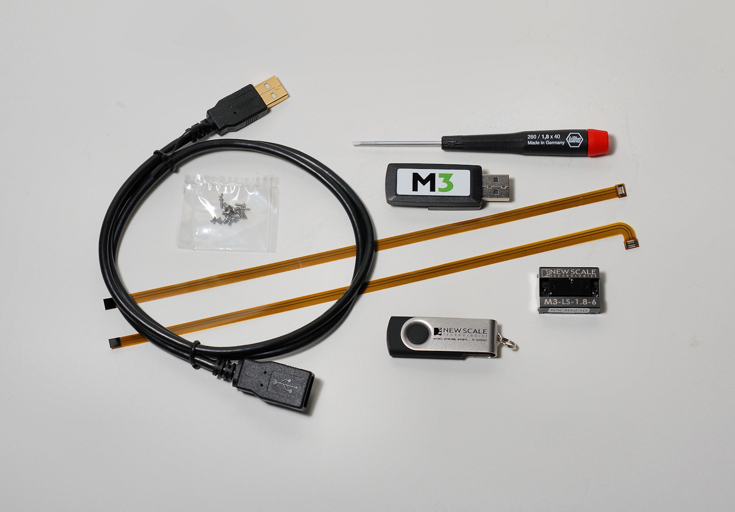
DK-M3-LS-1.8-6 Kit
- One M3-LS-1.8-6 Smart Stage with integrated controller, 6 mm travel
- One M3-USB USB adapter
- One straight flex cable, 250 mm length
- One angled flex cable, 250 mm length
- New Scale Pathway software
- Mounting hardware kit
Additional Developer’s Kits
Multi-axis developers kits are available at electroverge (USA only). Outside the USA, contact us or your local distributor.
M3 Modules and Volume Pricing
M3 modules (single units to production volumes) are available online at electroverge (USA only). Outside the USA, contact us or your local distributor.
Specifications
|
Model |
M3-LS-3.4-15 | M3-LS-U2-8 | M3-LS-1.8-6 |
|---|---|---|---|
| Description | Longer travel, higher load capacity Linear Smart Stage: micro positioning stage with built-in controller | High-speed Linear Smart Stage for high-volume applications: micro positioning stage with built-in controller | Ultra-compact Linear Smart Stage: micro positioning stage with built-in controller |
| Data sheet (PDF) | M3-LS-3.4-15 data sheet with drawings (PDF) | M3-LS-U2-8 data sheet with drawing (PDF) | M3-LS-1.8-6 data sheet with drawings (PDF) |
| Travel Range (Stroke) | 15 mm | 8mm | 6 mm |
| Dimensions | 32 x 32 x 11 mm including controller | 32 x 32 x 10 mm including controller | 29 x 20 x 9.5 mm including controller |
| Mass of Smart Stage (including controller) |
30 grams including controller 36 grams (+ cable + connector) |
15 grams including controller (note 1) |
8.4 grams including controller |
| Max moving mass (vertical) (note 2) |
100 grams | 5 grams payload mass recommended (note 3) | 10 grams recommended |
| Max moving mass (sideways and horizontal) (note 2) |
200 grams | 40 grams payload mass recommended (note 3) | 20 grams (offset < 10 mm) recommended |
| Force (operating) | 1 N |
>= 0.3 N holding force |
0.2 N |
| Speed (at operating force) | > 4 mm/s | 35 mm/s | 5 mm/s |
| Duty cycle | 50% max recommended | – | – |
| Closed-loop performance | |||
| Resolution | 0.5 μm with absolute encoding | 0.5 μm with absolute encoding | 0.5 μm with absolute encoding |
| Bi-directional repeatability | < 5 μm | ± 5 μm | < 5 μm |
| Accuracy | < 20 μm | ± 10 μm | < 20 μm |
| Input Power (note 4) | 6 VDC 5 W typical at 4 mm/s, 1 N load, closed-loop < 0.2 W quiescent |
5 VDC (4.75 V to 5.5 V)
|
3.3 VDC < 0.75 W typical at 5 mm/s, closed-loop (2 W max.) |
| Mechanical Stage | |||
| Static parallelism | < 30 μm | < 30 μm | < 30 μm |
| Run-out | < 10 μm | < 10 μm | < 10 μm |
| Pitch and yaw | < 1 mrad | < 1 mrad | < 1 mrad |
| Absolute max load | 10 N | see data sheet | 10 N |
| Linear slide features | Crossed roller bearings with high stiffness | Crossed roller bearings with high stiffness | Uniform and very low friction even under high direct loads and side loads. Six ball bearings in a kinematic “v” guide-way eliminate cage creep and friction spikes. |
| Environment | |||
| Relative humidity | < 70% | < 70% | < 70% |
| Operating temperature (note 5) |
+5 °C to +40 °C | -30 °C to +70 °C | -30 to +70 °C (note 3) |
| Storage temp. | -40 °C to +85 °C | -40 °C to +80 °C | -40 to +80 °C |
| Lifetime | – | 50 km travel (Note 6) | >10 million random moves while not exceeding 1.2 km total travel (note 7) |
| Compliance | CE / RoHS | RoHS / CE pending | CE / RoHS |
| Controller | embedded | embedded | embedded |
| Control interface | Directly via I2C or SPI serial interface Indirectly via USB adapter to PC |
Directly via I2C or SPI serial interface Indirectly via USB adapter to PC |
Directly via I2C or SPI serial interface Indirectly via USB adapter to PC |
Note 1: For the M3-LS-U2-8 smart stage, moving mass of the stage carriage without payload is ~6 grams
Note 2: Higher moving mass is possible but affects performance and lifetime
Note 3: For the M3-LS-U2-8 smart stage, torque due to gravity of the payload calculated from center point (see the coordinates in the data sheet PDF) on the carriage is recommended to be within 1.5 Nmm. Also recommend center of gravity of the payload above the carriage surface to be <=15 mm.
Note 4: Power depends on input voltage, speed and load
Note 5: Speed and force reduced at lower temperatures within the range
Note 6: Tested horizontally, with 20 grams load offset 8.75 mm at reverse position
Note 7: Corresponds to 10 million moves with an average random move of 120 µm. Lifetime depends on the application and use case. Please consult the factory to discuss your specific system design.
Documentation
Download CAD files, New Scale Pathway software and programming guides (registration required)
Learn more
The M3 Smart Module Platform
M3 Smart Modules integrate a piezoelectric SQUIGGLE® micro motor, precision mechanical guide system, position sensor, microprocessor, and drive electronics into one tiny package. Eliminating the need for external controllers, they offer the smallest system size and easiest integration into OEM systems.
Custom Engineering
We use our configurable M3 Smart Module platform to develop custom motion modules and systems that meet your exact requirements. We also develop full-custom micro motion systems. Ask us about a motion system feasibility study, the first step to faster, lower-risk product development.