
Resolution, accuracy, repeatability, and precision are critical requirements of motion systems. They fundamentally impact system complexity, cost, and development time. Understanding these terms will help you refine and optimize your instrument requirements.
At a high level, the common “dart board” illustration is useful to visualize the meaning of accuracy, repeatability, and resolution.
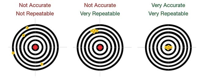
- Accuracy: How close is the actual position to the target position? (In the illustration: The distance a dart is from the center, or “bull’s eye” target.)
- Repeatability (often called precision): The variation of actual positions after several attempts to achieve the target position. (In the illustration: The grouping of darts after trying to hit the bull’s eye.)
- Resolution: The smallest increment of motion a system can achieve. (In the illustration: The skill of the thrower to adjust their aim and incrementally place darts vertically or laterally on the board.
When we consider these terms with respect to a motion system such as an M3 Motion Module, it’s important to understand the four elements of the motion system that we will use in the definitions:
A motor – produces rotary or linear movement in a mechanical stage, lens holder or actuator tip. For this article, we will use a piezoelectric motor.
An internal sensor (position encoder) – measures the rotary or linear position of the stage
A drive circuit – energizes the motors
A digital controller – reads position from the encoder and commands the motor to move to a target position.
Position Resolution
Position resolution is the smallest incremental movement that can be generated by the motion module. Position resolution can be open-loop or closed-loop.
Open-loop resolution is the smallest commanded movement that the piezoelectric motor can achieve in response to an input signal. For most M3 modules, open-loop resolution is tens to hundreds of nanometers. Open-loop steps of piezo motors are generally much smaller than the resolution of the position encoder. However, the motor steps have poor accuracy and repeatability.
Closed-loop resolution is the smallest commanded movement that the digital controller can achieve using its closed-loop algorithm. In practice, closed-loop resolution is the minimum movement that can be detected by the position encoder embedded in the module. For M3 modules this encoder resolution is typically 500 nanometers.
Another consideration when looking at resolution is that position encoders can be incremental or absolute.
Incremental encoders are the simplest. In use, they must first be “homed” to locate a fixed zero-reference position. They determine absolute position by counting encoder steps as the stage moves relative to the home position. A power-off event causes loss of counts and loss of absolute position, and the encoder must be re-homed.
Absolute encoders are more complex. They directly measure absolute position without the need for homing. This is desirable for many reasons, including faster instrument power-up and initialization; eliminating the need for a zero-reference position that might interfere with instrument hardware; and the ability to store critical position settings in memory and more easily reproduce them.
Position resolution determines the limits of the system’s accuracy and repeatability. However, a system can have excellent resolution and still have low accuracy and repeatability.
Accuracy
For M3 motion modules, position accuracy is only applicable to closed-loop operation. It is the variance between the stage position achieved by the digital controller, and the stage position as measured by an independent measurement method.
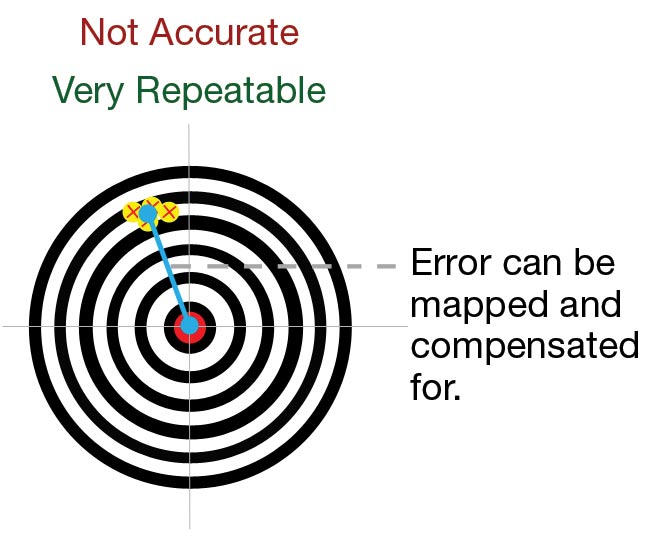
This variance is mapped over the range of motion. A significant component of the accuracy variance is repeatable and can be mapped, stored in memory, and corrected for by commanding offsets. This process, called calibration, improves accuracy up to the limits of system repeatability and resolution.
Referring to our dart board example, a person with a repeatable throw can improve their accuracy by adjusting their aim down and to the right.
Repeatability
Position repeatability (often called precision) describes how well the motion system returns to a consistent position in response to repeated commands to reach that target position. Repeatability can be bi-directional or unidirectional.
For bi-directional positioning, the target position can be approached from either direction. The total variance is measured.
For uni-directional positioning, the target is approached from the same direction every time. Unidirectional positioning provides better repeatability, at the cost of extra moves.
Let’s look at an example. The graphs below show accuracy and repeatability measurements for an M3-F Focus Module with 0.5 micrometer closed-loop resolution. The embedded digital controller moves a lens to a series of target points, both in forward and reverse directions, over its full travel range of 1.5 mm. At each point the position was also measured with an external laser position sensor (Keyence). Note that the origin is position zero, with zero error. The process was performed twice.
The X axis shows the recorded lens position after each commanded target move. The Y axis shows position error measured by the external Keyence sensor for each target position. This is the difference in lens location as measured by the external sensor vs. the internal sensor.
The vertical difference between curves is the repeatability. The difference between two curves of the same color (indicating travel in the same direction) is uni-directional repeatability. The difference between curves of different colors (indicating travel in opposite directions) is bi-directional repeatability.
What is the practical application of this? Consider an auto-focusing camera, using an M3-F module, where the image processor collects a series of evaluation images along the optical axis of the lens. One of these images has the sharpest focus, as determined by image analysis. A typical hill-climbing search algorithm will collect images past the sharpest focus and command the lens back to the position of best focus. Fast convergence to best focus requires repeatability.
A more detailed description shows that when moving in the forward direction, the last image is taken at position 1500 µm on the pink curve. If image analysis determines that the sharpest focus is at 850 µm (on the X axis), we need to move the lens back to the 850 µm position to achieve best focus. We have two options:
Option 1: Reverse direction and stop at the 850 µm position. The actual variance from the optimal position could be as much as 7 µm (bidirectional repeatability). This is the fastest option.
Option 2: Reverse direction, travel past the 850 µm position, and then move in the forward direction to stop at the 850 µm position. The variance from the target position would be reduced to approximately 1 µm (unidirectional repeatability). This takes longer but more precisely reproduces the sharpest image.
The camera systems engineer can evaluate and select the best option. For many cameras, detectable changes in sharpness require movements greater than 10 micrometers. The M3-F bidirectional repeatability is more than sufficient to find and repeat the best focus position.

Understanding resolution, accuracy, repeatability, and precision of motion systems will help design engineers to achieve the performance they need without excess complexity, cost, and development time.
This article was originally published in Photonics Spectra, October 2022.
Learn more
-
- Read deeper: open-loop vs. closed-loop positioning
- Learn more about what’s inside an M3 module: M3 Motion Modules integrate a motor, mechanics, and drive electronics. They have small size with with high resolution and repeatability. When embedded into precision instruments, they reduce development time for instrument designers.
- Browse the linear stages, actuators and rotary stages in the M3 Module line.

Technical Review By
Stefan Friedrich
Marketing Manager