Rev. 7
Prior to purchasing the M3-FS or M3-F Focus Module Developer’s Kit, you should verify compatibility of configuration to your lens and imager format. This design note outlines how to validate system compatibility.
1. What do you need to know?
You will need to know the following basic parameters to understand whether your optic and imager components will work with the M3-FS or M3-F developer’s kit:
- Mounting hole pattern
- Lens thread
- Lens dimensions
- Lens focal length for your imager size
- Lens travel required
- Imager array thickness (mounted) and diagonal dimension
- Lens viewing angle
2. Mounting requirements
The M3-FS and M3-F modules in the developer’s kit are designed with a base as shown in Figure 1. Check the dimensions to ensure that no interferences to components on your imaging board exist. Holes are compatible for clearance of M1.4 or UNF 0-80 screw. If hole patterns are not compatible, you will need to provide screw mounting holes or adhesively mount the module onto the board surface.
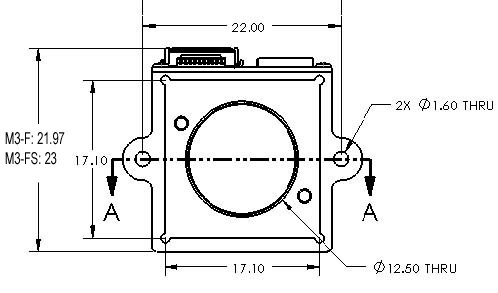
Figure 1: The M3-FS and M3-F Developer’s Kit module mounting footprint
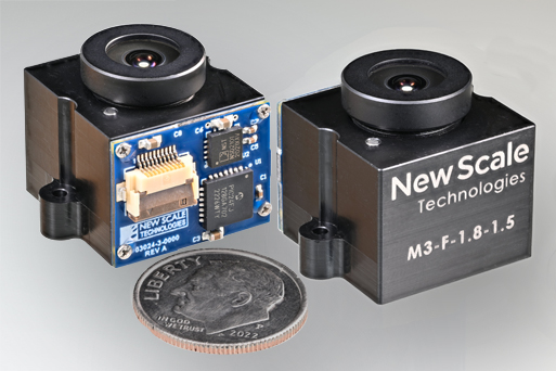
3. Position of the lens relative to the image sensor
A typical image sensor array thickness can be 0.7 to 1.0 mm. You need to establish the board-mounted position of the top of your image sensor array, as well as its diagonal image dimension (Figure 2). This information can be provided by your image chip or camera board supplier. The infinite focus position to the top surface of the sensor should establish the lower position of the lens assembly for the lens you require.
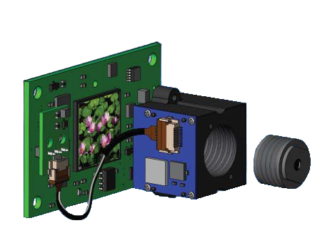
4. Lens Specifications
The maximum travel of the M3-FS or M3-F module in the developer’s kit is 1.5 mm. The upper and lower range of this is a factory setting and established to avoid over-travel of the lens barrel. The zero reference position places the base of the adjustable M3-FS or M3-F barrel at 2.25 mm from mounting base (Figure 2). This travel results in a fully extended travel limit of the base of the barrel at 3.75 mm above the mounting base. Full travel range for your optical system must be less than or equal to 1.5 mm.
The M3-FS Module has a threaded barrel to allow insertion of M16X1 mm threaded lenses. A lens adapter to accept M12X0.5 mm lenses is included in the developer’s kit.
The M3-F Module has a threaded barrel to allow insertion of M12X0.5 mm lenses. A lens adapter to accept M8X0.5 mm lenses is available (not included in the kit).
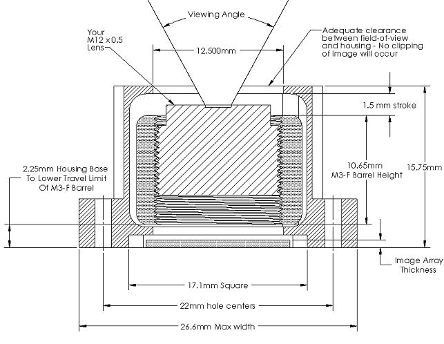
Figure 2: Example of geometry considerations using the M3-F Developer’s Kit module dimensions. Download the solid model for dimensions of the M3-FS or M3-F module (registration required).
Additional basic information that you need from your lens provider includes outer dimensions, infinite focus distance for the imager sensor array geometry and viewing angle. With the lens placed in a position of infinite focus, ensure that the field of view angle does not intersect the module housing (Figure 2). This will ensure that clipping of your image will not occur.
For lenses that include a flange (Figure 3), interference with the outer M3 housing needs to be checked at this lowest lens position as well.
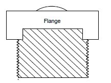
Figure 3: Lens with flange
To allow you to perform a geometric analysis with your image array and lens combination, a cross-sectional dxf and pdf file of the M3-FS and M3-F modules are available for download here. (registration required).
5. Example lens and image sensor array formats
Edmund Optics is a reputable supplier of high-quality lenses, many of which are available from stock. The HEO Series M12 lenses and Blue Lens Series M12 lenses, offer M12 mounting with focal lengths from 2mm to 25mm. Several different apertures are available in this product series. We recommend picking a lens with a mass of <5g. A fixed orientation may allow for heavier lens operation with our focus modules. Contact us if you would like us to review your exact requirements.
The table below lists other examples of lens and sensor configurations that are suitable for use with the developer’s kit. Visit Sunex online to search for lenses and order samples.
| Model number | Imager format (diagonal) | Thread |
|---|---|---|
| Sunex DSL853(A,B or C) | 1/2″ (16 mm) | M12x0.5P |
| Sunex DSL935 | 1/1.8″ (8.89 mm) | M12x0.5P |
| Sunex DSL944 (requires optional adapter CMT0805-1205 from Sunex) | 1/2.5″ (7.2 mm) | M8x0.35-6h |
6. Conformance Information
The M3-FS and M3-F modules conform to the following standards:
- EMC Directive: 2004/108/EC
- Generic Emissions Standard: EN 61000-6-3: 2007
- Product Specific Emissions: EN 55022
- Generic Immunity Standard: EN 61000-6-1: 2007
- Immunity: EN 61000-4-2 Electrostatic Discharge, EN 61000-4-3 Radiated Susceptibility, EN 61000-4-8 Magnetics
FCC Rules and Regulations:
- United States 47 Code of Federal Regulations Part 15 – Electromagnetic Emissions, Class B Devices
Standards:
- ANSI C63.4-2003, Methods of Measurement of Radio-Noise Emissions from Low-Voltage electrical equipment in the range of 9kHz to 40GHz.
- Section 11.0 Measurement of Information Technology Equipment (ITE)
RoHS Compliance:
This document certifies that the products listed in this document and manufactured by New Scale Technologies do not to the knowledge of the certifier contain the substances listed in the table below in concentrations exceeding the Maximum Control Value (MCV), and will be compliant as of the date listed.
7. Lens installation and alignment
Install your lens using the threaded inside diameter of the M3 module. The M3-FS accepts a maximum M16 diameter lens, or an M12 lenses with a standard adapter. Smaller lenses may be feasible depending on the optical design. The M3-F accepts a maximum M12 lens directly.
For typical camera integration, “active alignment” is required to align the optical centerline of the lens orthogonal to the image sensor by moving the M3 module and lens as a single assembly.
After alignment, the base of the module is typically secured to the image sensor board using shims, adhesive and screws. The lens back focal distance is then set by rotating the lens in the threads and securing it with a small amount of adhesive in the threads.
For additional M3-FS and M3-F module questions
Please refer to the M3-FS and M3-F page for developer’s kit specifications. Developer’s kits are available to qualified OEMs as part of a development program with New Scale, or for purchase from online distributors.
If you have additional questions regarding the Developer’s Kit, or for custom design requirements, please contact us or call (585) 924-4450.
Technical Review By
Stefan Friedrich
Marketing Manager

